
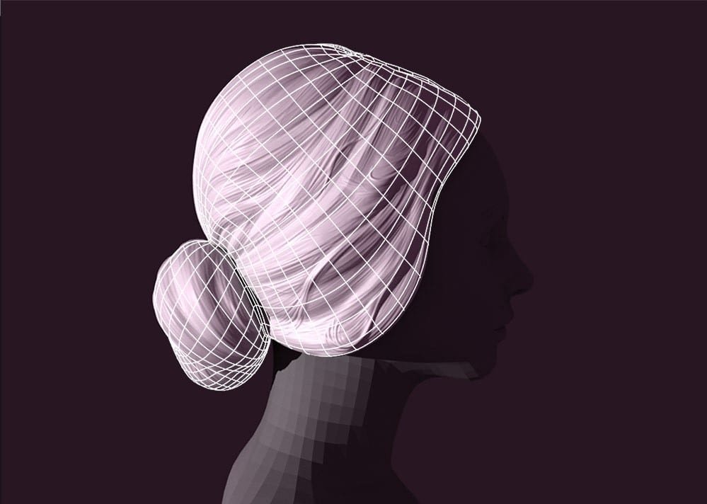

We finished the Retopology of our object in Maya and obviously, none of the details of the model that we did in Zbrush remains since what we have now is a very low polycount, then some of you may wonder… what is the retopology used for whether in the end, we have sacrificed certain volumes and all the details?…how can high detail be projected onto such a low-density mesh and preserve an orderly mesh with well-defined UVs?…
If what we want is to have a low-poly mesh and high-poly details to make the render benefit from this brotherhood… we are talking about Displacement Maps . Follow us on this journey and we will try to see how these maps are generated in Zbrush and taken to Maya to be used by the renderer (Arnold).
Table of Contents
Point 1: Moving the Retopo from Maya to Zbrush

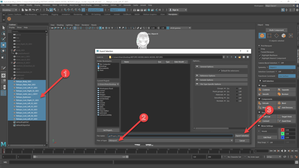
- Select all the meshes you need to move to Zbrush from the Outliner.
- File > Export Selection… and select OBJexport as “Files of type” to get the .obj file that is compatible with Zbrush
- Select the Destination Folder, add your file name and hit the Export Selection.
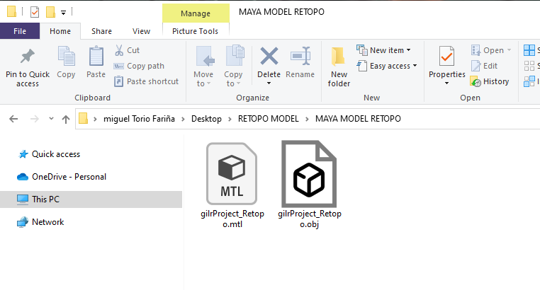
In the Destination Folder you will find two files…one is the .obj that is the one to use in Zbrush, and the other one, the .mtl, is the material data…simply ignore it.
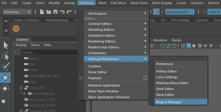
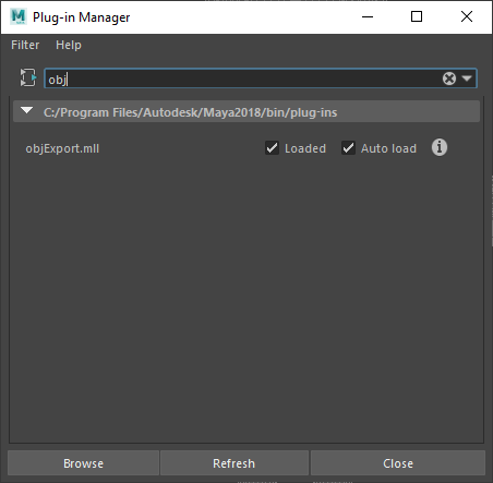
In case you cannot find the OBJexport option (Files of type) in the Export Selection screen, then you can get it by adding the plugin from the Plug-in Manager: Windows > Settings/ Preferences > Plug-in Manager and then look for obj… thick the two options to load it in your Maya.
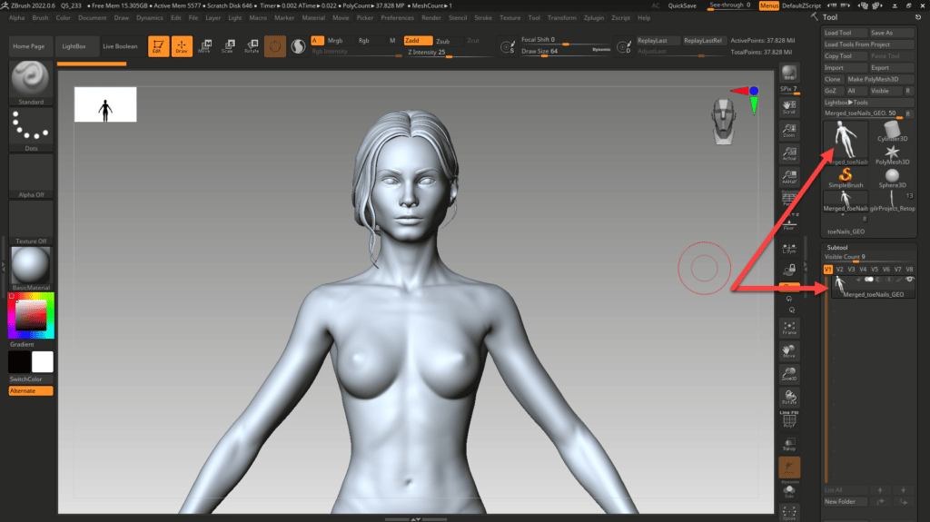
We go to Zbrush to open our High-Resolution model and we import the Low-Res model.
In order to do this we follow the next steps:
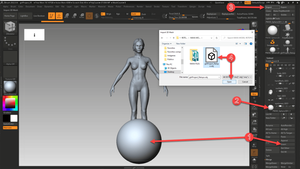
- The Import will overwrite the mesh we select in our Subtool list therefore we create a dummy object:
1.1. Insert > Select the sphere or any other figure. This will be added in to your Subtool list. - Select the inserted figure from the Subtool List.
- Press Import from the Right panel (Tool panel).
- Select the Maya .obj and hit Open.
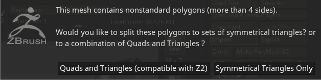
Important: If you get the below message when importing the model into Zbrush, it means your topology has some issues …an edge with zero length, non manifold geometry (any edge shared by more than two faces), faces with more than 4 sides, faces with zero geometry… If you accept this message Zbrush will modify your mesh in an unwanted way, therefore we recommend going back to Maya and using the Mesh > Cleanup to ensure all is top-notch.
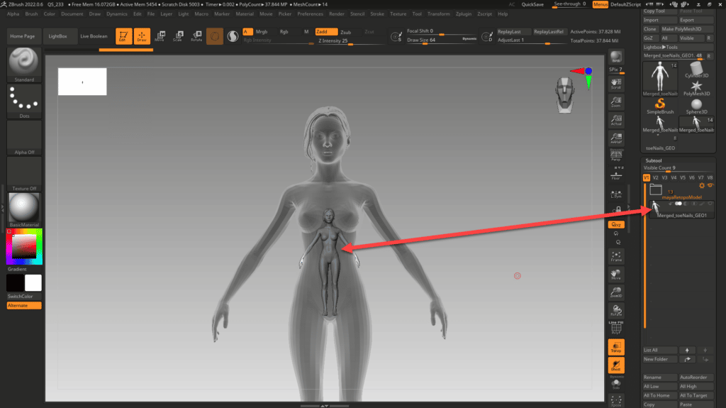
Our Maya model is huge!! and the High-Res is very tiny… in order to project the High-Res over the Lo-Res, both need to overlap perfectly, therefore we need to make them match…
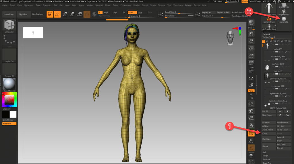
The intention now is to have the imported model in its own space for the work we are going to do, therefore we COPY the tool and select one of the places we have above; once selected just needs to press PASTE to have it within the tool list of the new space.
Remember to remove the geometric figure that was already there from the Subtool List with the option Delete (this option is near the COPY one).
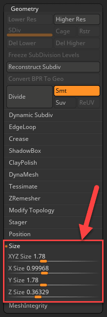
We are going to re-size both to 1.78 cm of high (100 times lower than real) and also ensure both are located in the same position within the Zbrush working space (0,0,0).
We go to Geometry > Size and we select 1.78 in the XYZ slider. I prefer to scale it in this way as it is less aggressive for the mesh.
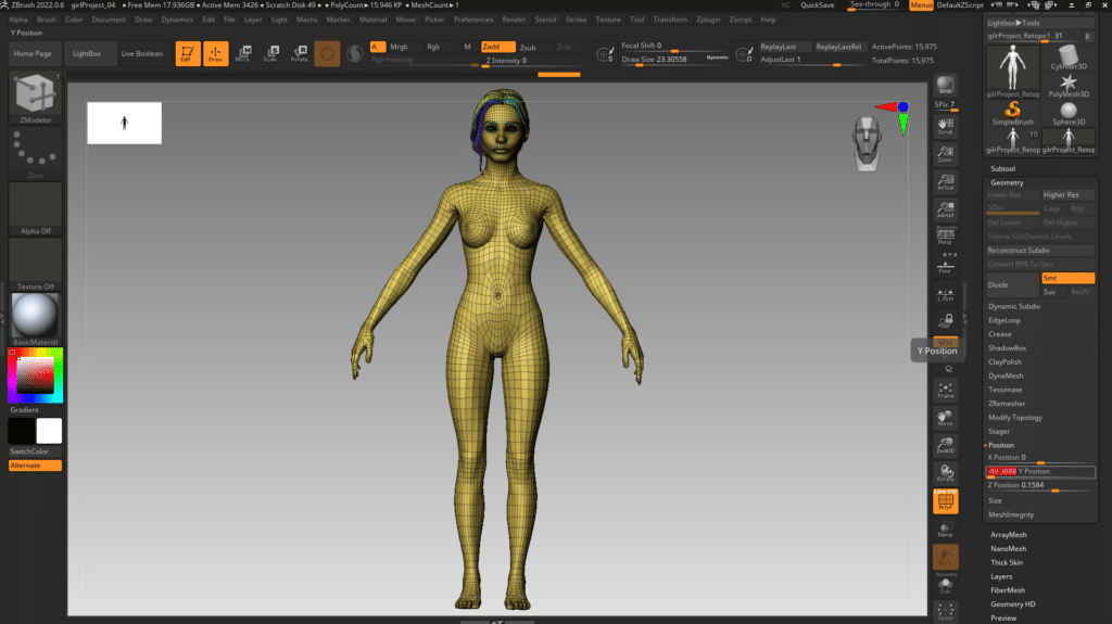
The model is now in the required size, then we are going to ensure the entire model is seated in the position (0,0,0).
This can be achieved by going to Geometry > Position and moving all the sliders to zero.
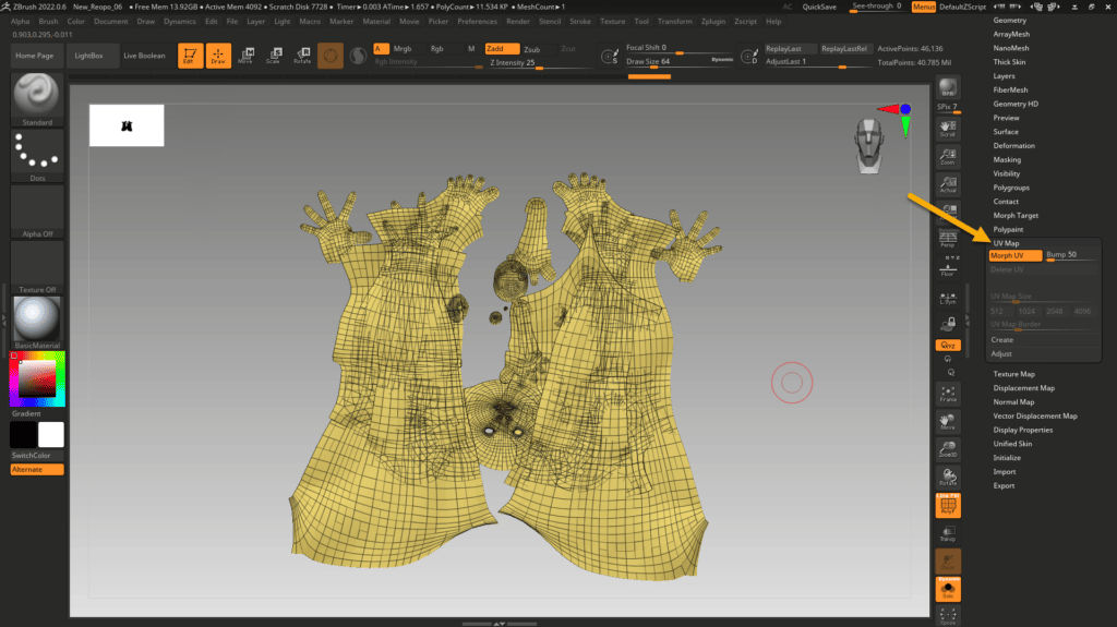
One of the things I tend to review before starting the process is to verify I got the UVs from Maya. This can be reviewed on
UV Map > Morph UV. As we got UDIMS they will appear overlapped in the same tile…by hitting the same button you will get back the 3D view.
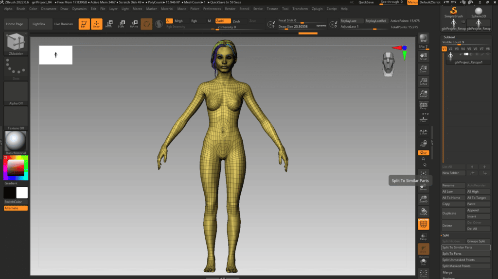
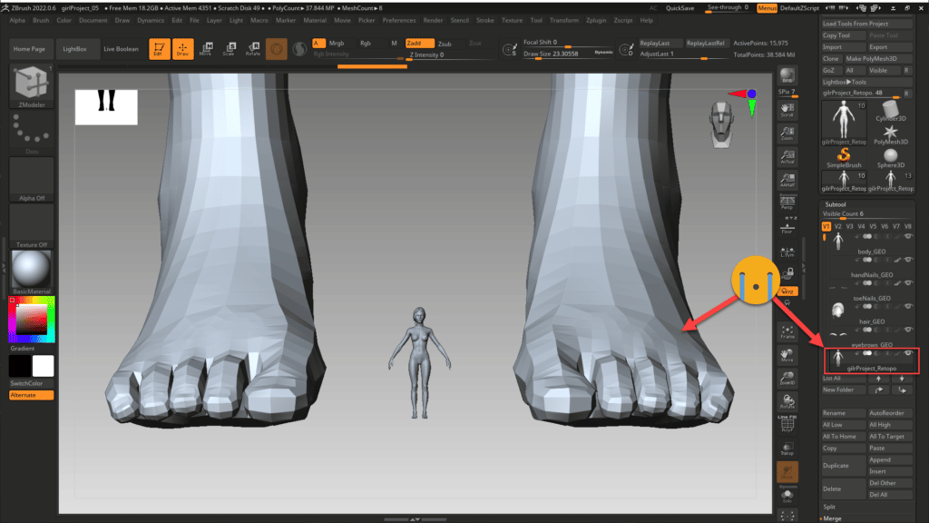
The Low-Res Model is now ready in size and position, then it can be split into the same parts we had in the Maya Outliner.
Subtool > Split > Split To Similar Parts
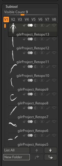
I tend to keep the related subtools in Folders, then we can create a New Folder and drag (LMB) all the subtools inside.
Finally, we are going to have all the pieces inside our Folder as above… but in future, if you want to split the subtool, would be better to create the folder first, drag the tool there, and then split it … all the subtools will remain inside the folder .
We need to do something similar with the High-Resolution model…
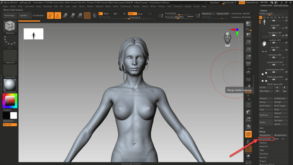
The High-Res model is already split in Subtools, therefore we need to merge them all to get a full-body model able to resize & reposition.
This can be achieved by selecting all the Subtools that we require to get merged and hitting Merge > MergeVisible.
A message will pop up saying “This is not an Undoable operation. Press ‘OK’ to continue or ‘CANCEL’ to abort“. This is not going to destroy your model then select “OK“, it simply generates a NEW Subtool with all the pieces visible in the canvas. The selected Subtools will remain untouched in the current Subtool List and the new item will appear up in a new working space.
Now by using the COPY-PASE options, we move the new tool into the workspace we have the Low-Res and we apply the same size and position to make them identical.
This is how I found the model when I added it to the workspace….and below is what I got after resizing & reposition it.
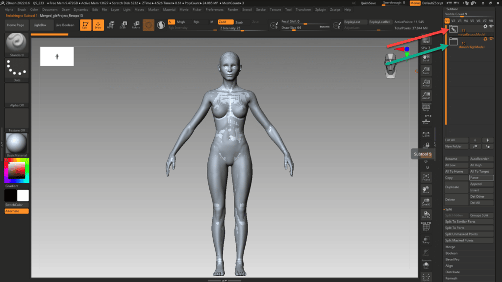
We leave visible the Low-Res (Selected & Visble) and the High-Res just Visible and we can see the differences between them.
Point 2: Projecting High-Res into our Low-Res
We are going to apply a Projection with just 1 Subdivision in the Low-Res and we will do it twice. This will help us to start readjusting the lower subdivisions in case the volume needs to be corrected.
We are going to bring some notes about the Project Features…
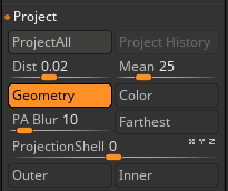
We will leave the features as per default, but I added here what each option does in general terms in case you prefer to tweak something.
Projection Options in Zbrush extracted from the Official Tutorial Page:
| Project All: | The Project All operation will project sculptural detail from a source mesh to a target mesh. The meshes don’t have to have similar topology but should be broadly similar in shape. Source and target meshes should be SubTools in the same list, and for best results should be the only two visible SubTools. The other settings in this section will affect the result of the projection. |
| Dist: | The Dist setting affects the projection distance for each normal from the source mesh to the target mesh. A setting of 1 is the maximum. |
| Mean: | The Mean slider will take the average of the point difference between the target mesh and to source mesh and set this as the plateau for Project All. |
| PA Blur: | The PA Blur will apply to smooth the projection. Setting the slider to 100 will apply the strongest smoothing. |
| ProjectionShell: | The ProjectionShell slider will establish the target mesh start point for ProjectAll. |
| Farthest: | The Farthest switch sets the ProjectAll operation to project from the target mesh to the farthest points of the source mesh. |
| Outer: | The Outer switch sets the ProjectAll operation to project from the target mesh to only the outer points of the source mesh. If there is any of the source mesh inside of the target mesh then that part will not be projected. This option is automatically turned on if ProjectionShell is set to a negative value. |
| Inner: | The Inner switch sets the ProjectAll operation to project from the target mesh to only the inner points of the source mesh. If there is any of the source mesh outside of the target mesh then that part will not be projected. This option is automatically turned on if ProjectionShell is set to a positive value. |
Procedure:
Division 1: We did not Divide our Maya mesh and we hit ProjectAll. I always recommend reviewing the Low-Res mesh and looking for possible errors… In case you find a spot that is going crazy after the projection, you can mask it to avoid getting affected by the Project tool.
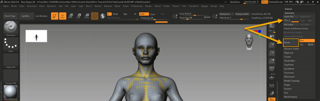
Division 2: Remember to unmask, if any, the places you wanted to protect before subdividing the model… and then Divide the Low-Res model! and apply two more Projections.

Division 5: Now we can go directly to the 5th one to print the High Detail and hit the two more times ProjectAll button…this time Zbrush will take longer depending on the PC you have. The above is the result of the exercise in the body mesh.
Now we have all the detail in our new Topology!!…then just we need to create the Displacement Maps for our UDIMS to be applied over the smooth version of our Low-Resolution in Maya.
Point 3: Creating the Displacement Maps
The details are now part of our new topology, therefore we can generate the Displacement Maps of our meshes.
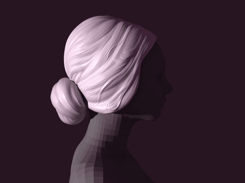
We are going to use the hair as it has some smooth details that will illustrate the process better.
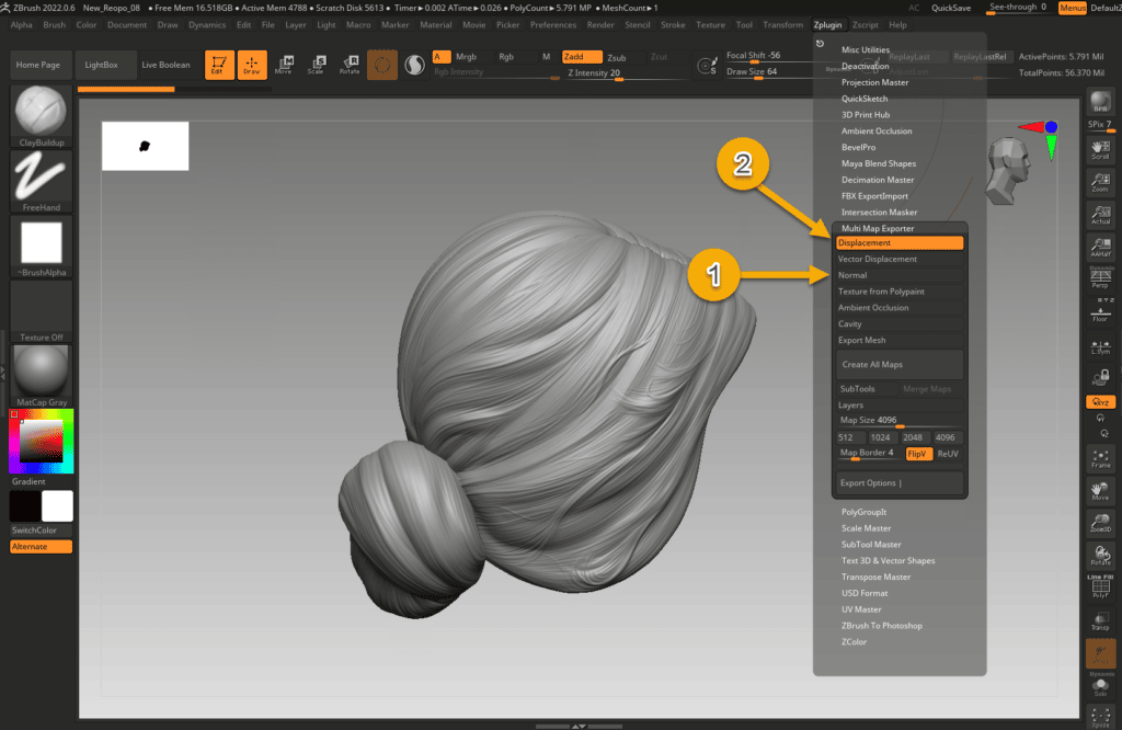
The tool to use is Zplugin > Multi Map Exporter.
By default the Normal map is selected then we proceed to uncheck it and select Displacement instead.
This will be our selection for our 4K Displacement maps:
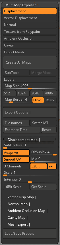
Displacement Options selected:
| Map Size: | 4K map size (4096) as we are looking at this level of detail. |
| FlipV: | This option flips the maps vertically to be aligned to the expected position in Maya as Zbrush flips the UVs by default and this option corrects it. |
| Map Border | By default is 4 and it seems it is to somehow dissimulate the seams…I did not experience any issues with the limits of the UV map therefore we leave it as default. |
| Export Options (Section) | Displacement Map (Section) |
| SubDiv level: | We select level 1 as we are going to work over the lower subdivision in Maya that is also 1. |
| Adaptative: | Zbrush defines it as “Adaptive Raycast Scan Mode” which is not very helpful. It seems might add some extra effort from Z when creating the maps…for this model, it will increase almost in 3 min the processing time to get the Maps… but we want to have a try as Zbrush prays it will create a more accurate map in detailed zones…We are going to create the maps with and without for you to see if it is worth it. |
| DPSubPix 4: | It divides the higher subdivision by the specified number during the map generation…in my case will be a huge amount of memory, but again, Zbrush mentions that it will produce higher quality maps although this time it will affect considerably the time taken to generate and export the maps….we moved it to 4 and we will see if it is worthy later in this tutorial… |
| SmoothUV: | UVs are smoothed before the map is generated. This is a must. |
| Mid: | Zbrush recommends this to be 0 in case we work with 32 bits to get better results…and 0.5 in case of 16 bits. |
| 32 Bits + ext: | Export at 32-bit Floating-Point map for better results and EXT as output file format as recommended. |
| 3 Channels: | We are not going to use this as Arnold does not require it…the map is going to be used as alpha. |
File names is another option that can be used to record the map in the UDIM convention.
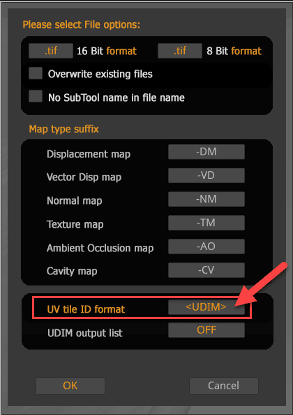
Click where the arrow points and you can move it to <UDIM> format. We are just going to use UDIM despite the mesh has one or more than one UV tiles. This format will help Maya to recognize the UV easily.
Now is time to hit Create All Maps button, select the folder where to place it and wait…
I know there are many factors involved in the Time taken results… but it’s just to show you a certain dependency between the time and the selected options.
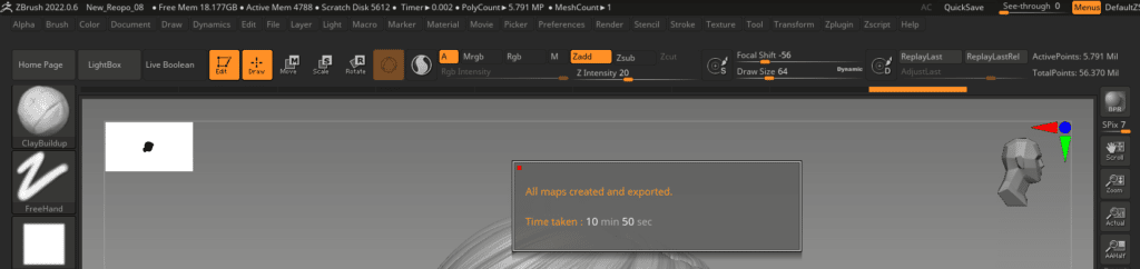

The above configuration took 10 min and 50 s just for the hair mesh Displacement Map. We selected Adaptative + DPSubPix 4 and this is the result (above).


3 min and 45 secs just for the hair mesh Displacement Map…(Adaptative + DPSubPix 1)
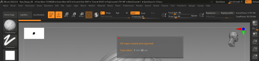
1 min and 35 secs just for the hair mesh Displacement Map…(Adaptative Turned Off + DPSubPix 1)
As far as I can see, the changes in these two variables are negligible for this mesh.

We did one last Test with (Adaptative + DPSubPix 1 + SmoothUV Turned off) and this seems to be affected negatively…therefore SmoothUV will be Turned ON in our selection.
Finally, we have the .ext file with the UDIM nomenclature DM1001.exr, just one file!, as this is the hair mesh that uses just one UV tile…in the body mesh we have 4 UV tiles then this plugin will create 4 different exr. files, one for each tile… we will apply the same configuration for both in Maya.
Point 4: Linking the Displacement Maps to our mesh in Maya
We prepared a light setup in Maya and import the hair mesh into the scene. The next step will be to assign a material to the new mesh.
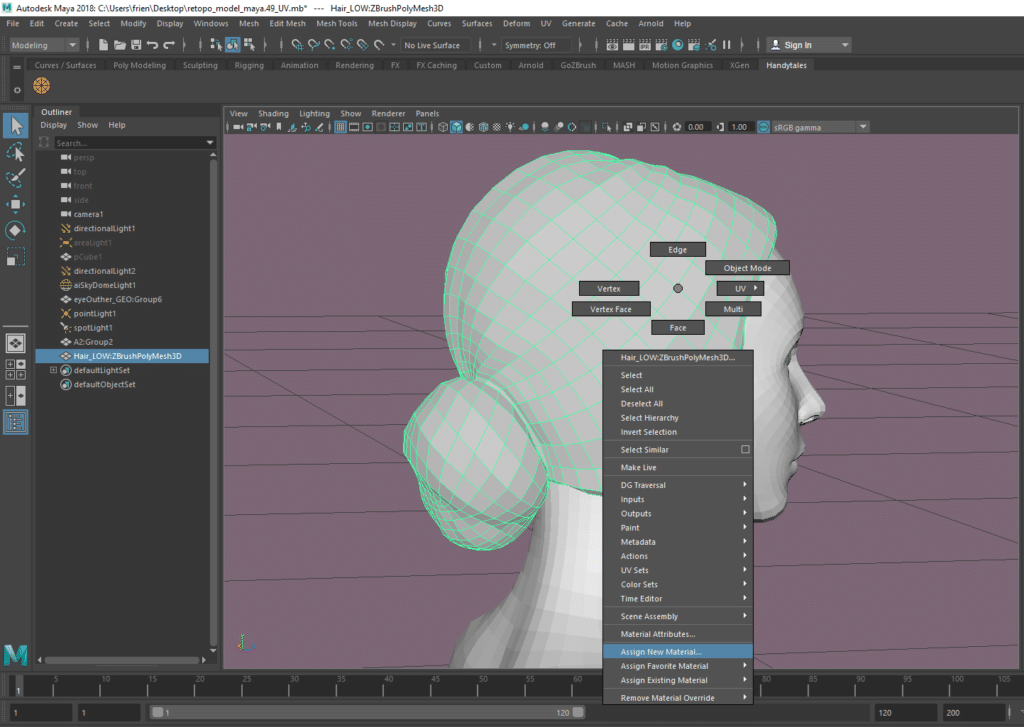
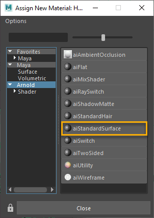
Select the mesh, then RMB and select “Assign New Material” and the below screen will emerge. Select the aiStandardSurface as material (you can select any other material type).
Lets go now to Hypershade Window!!

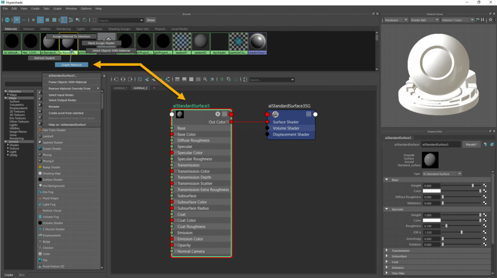
We need to select our Material from the Material watches, hold RMB and select Graph Network…This will bring your material node into the scene…and now we render the scene on Arnold…
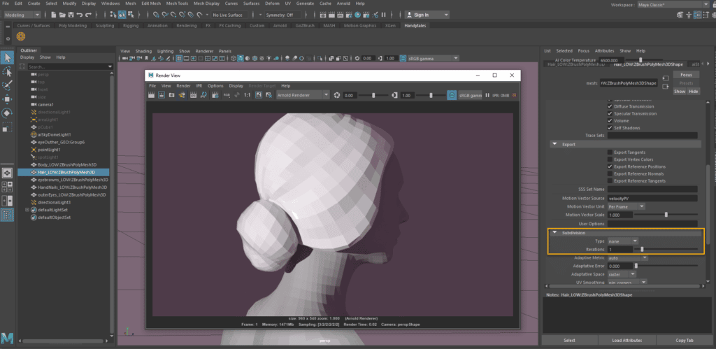
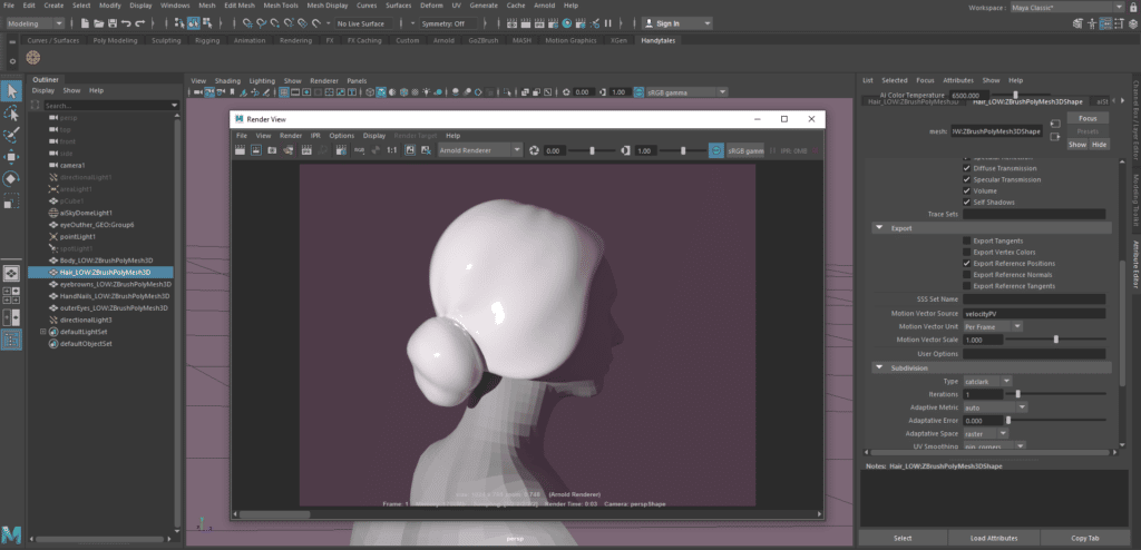
Arnold just captured what it is in the scene…if you want to see it smoother, then go to the YourMeshNameShape tag and visit Arnold> Subdivision > select catclark (catmull clark) as Type (it was none by default)… then hit again the render!!
It is very glossy…In order to corrected a bit, Select the aiStandardSurface material and change the Roughness to 0.5 within Specular.
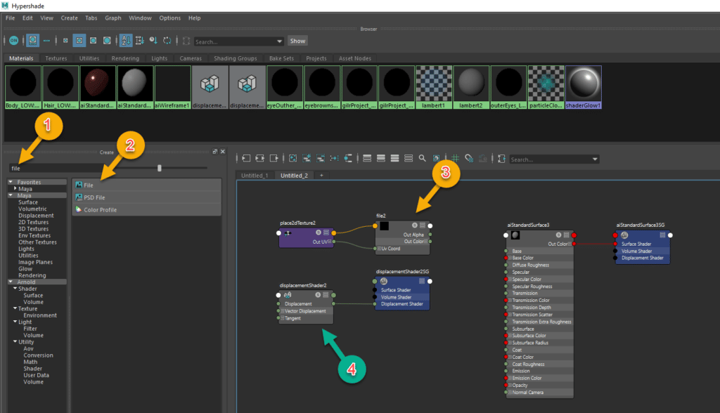
Time to add in the Hypershade canvas the elements we need to use to get applied Displacement Map into Maya.
- Look for the Node in the Search Bar (File & Displacement)
- Select File
- The Node will be automatically added into the canvas
- Do the same with the Displacement node
We have now the Displacement Node and the File Node in the Hypershade canvas as above. How they will be connected?… We generated the below GIF to illustrate how to get this done. There is another way to get this but for me, this is easier to understand as it is node-visible.
- The first step was to link the file with the Displacement just by dragging the mouse while pressing the MMB (middle mouse button) from the File2 node to the Displacement tag.
- Remove the Displacement Shader as we will use the material one (Select it and press your Delete button from the Keyboard).
- Connect the Displacement Node Output (Drag by LMB) to the Displacement Shader Input in the material Shader node.
- Go to the File Node to click in the Folder to select our Zbrush Displacement Map. If your mesh has more than one UV tile just select the 1001 and Maya will load all of them.
- Select within the same node, UDIM(Mari) in the UV Tiling Mode and check the Alpha is Luminance on Color Balance.
Point 5: Getting Ready with Arnold
We need to change some feature values to get our details a bit better on the Arnold Render.
We need to click in the mesh we are interested in and open the tag with the suffix Shape. Within this tag, we can see many dropdowns but we are now interested in the Arnold one that will offer some other options. The ones that interested us now are Subdivision and Displacement Attributes.
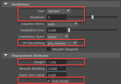
Subdivisions:
Type: This would need to be catclark as we saw it before in this post.
Iterations: This number should match the number of subdivisions you defined on Zbrush.
UV Smoothing: pin_corners works for me but if you have some black lines in the UV, you can try the pin_borders.
Displacement Attributes:
Height: In case you want to strengthen the details of your map then try to test something higher. Default 1 and we do 1.25.
Definition from Maya Autodesk: Controls the amount of displacement. Displacement_height can have either positive or negative values.
Auto Bump: Selected… this could save us some Subdivision Iterations…for instance if you had 6/7 Subdivisions on Zbrush, here you can define just 4 or 5…
Definition from Maya Autodesk: Autobump puts the high frequencies of a displacement map into the bump attribute so that you do not need as many Subdivision Iteration values. Autobump is visible to camera rays only by default. The visibility parameters let you make autobump visible to other rays (eg specular and transmission ) however that can increase render times.
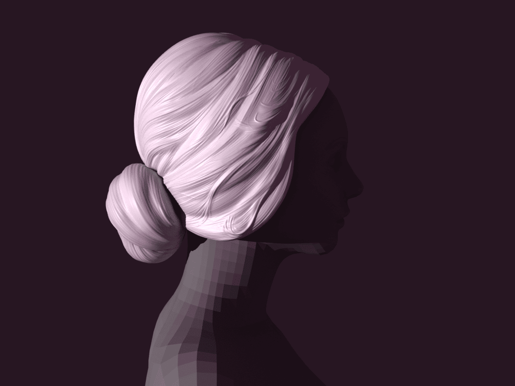
Now is time to render your Low-Res mesh with High-Res Detail !!.


Miguel Angel Torio
HandyTales Founder & CEO


188betdangnhap! Now they’re just being fancy. Hope their site lives up to the name. Let’s see… 188betdangnhap
Just signed up with betbrx and so far, so good. The interface is clean and I found something to bet on pretty quickly. Might be my new go-to. Check it out and see if you like it. Join NOW at betbrx
Lucky67 is pretty cool! Good way to spend some downtime. I’ve had some good experiences so far! Give it a shot at: lucky67
Yo 55666 bong88, need a reliable access point to Bong88. You got what I need? Fast, secure, and always up. Get in the game: 55666 bong88
Bingo lovers, listen up! Betplaybingo has some seriously fun games and the community is pretty chill. If you like dabbing and chatting, it’s worth checking out. Maybe you’ll even shout ‘Bingo!’ It’s over at betplaybingo!
Hey there! 20bets is giving me a wide range of sports betting options. They cover everything from football to e-sports and the odds are usually pretty competitive. If you’re looking to place some bets, you might want to check them out: 20bets
Just a heads up for anyone looking for 155betlogin. Make sure you’re using the correct verified site. Nobody wants to get phished! Always double-check the address. It’s over here 155betlogin
Bajilogin is pretty straightforward to use. No complicated hoops to jump through. Just log in and get going. Solid choice in my book! Easy access via this link: bajilogin
Had a little trouble finding the right login page for p828login, but once I got in, it was smooth sailing. Make sure you bookmark it! Access easily here: p828login
777xatq is pretty solid. Quick payouts and a good selection of games. I will definitely be going back. Visit: 777xatq
78bets… hmm. Could be my lucky number. Or not! But there’s only one way to know for sure to give it a try! Wish me good luck! 78bets
J168… looks sleek. It seems to run smoothly, but their customer support needs massive improvement. If you like risk taking try j168.
Yo, King79! Just signed up. Heard it’s the place to be. Fingers crossed for some lucky spins! Check it out here: king79
Kingfunapk is a fun way to pass the time. The app is easy to download and use. Definitely worth a look if you enjoy mobile gaming. Download it here: kingfunapk
Hey, if you are searching for reliable analytics on rong bach kim tv, this site has been very helpful. Check it out! rong bach kim tv
I’ve been trying ‘lucky47’ with Lucky47 and am having a blast! Great community and some really cool insights! You should check it out lucky47!
Alright, needing an easy way in? pg888login sorted me right out. No messing about, straight to the games. Good shout if you’re wanting to get straight to the action. Link here: pg888login
Joined tigamego88club the other day. Had some fun, good selection of games. Not too shabby for a bit of downtime. Click here: tigamego88club
Been having a go at sv88vip. A bit more upmarket, I reckon. Feels proper fancy. If you’re after some VIP treatment, give it a whirl. Find it here: sv88vip